
AEBoards Satellite (EC) Build Guide
Introduction
Hey! Welcome to this build guide for the AEBoards Satellite with Naevies Electro-Capacitive (EC) switches.
While there are many articles and guides on how to build a custom mechanical keyboard, this one is a little bit different. Instead of a Cherry MX switch and PCB (printed circuit board), we will be using EC technology. EC has been popular in the mechanical keyboard community for many years, particularly thanks to Topre mechanical keyboards and most recently, thanks to advancements in EC-capable PCBs and after-market EC-compatible components, such as domes, conical springs, and stem sliders.
For starters, I highly suggest viewing this guide on desktop.
Kit Contents
For this build, we will be using the following:
Precision screwdriver kit
Lubricants (e.g. Krytox 205g0)
Brushes for lubrication - any similar to these will do
Included: PCB, hardware (screws & standoffs), 70x EC switches
Cherry MX-compatible PCB-mount stabilizers
For this build, we are using Staebies V2.
Optional (quality of life improvements):
Pliers
USB-C cable (to connect your keyboard)
Stem holder (makes your life easier holding things)


A spread of the kits’ components:
Satellite keyboard case with plate and microfiber cloth
Staebies stabilizers and hardware (inside foam)
Bump-ons
26 units of M2 x 3mm screws for PCB underside
26 units of M2 x 3.5mm standoffs
26 units of M2 x 3mm screws for plate top-side
Gaskets (won’t be used in this build)
Constellation EC PCB and plate

Stabilizer Components
Stabilizers are generally comprised of housings, stem inserts, and wires. In the case of screw-in ones such as these, screws and washers for attaching the stabilizers to the PCB are also present.
In this photo, we have separated:
Left (blue): bag and extras
Middle (yellow): necessary stabilizer parts (4 stabilizers: 3x 2u and 1x spacebar)
Bottom (green): plate (8 units M3 x 5mm) and case screws (8 units M3 x 10mm)

A Note About The Plate
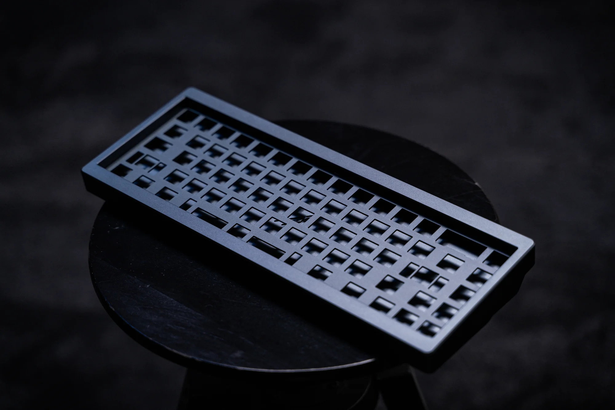
Depicted are two plates. They may look very similar, but they differ in key ways.
Top (EC): EC-compatible plate - has screw-holes that enable using standoffs between the plate and PCB. Top-mount tabs only.
Bottom (MX only): No screw-holes for standoffs. Top-mount and gasket-mount tabs available.
As you’d expect, we will be using the EC-compatible plate along with the EC-compatible PCB.


Case Prep
Attach the four, pill-shape bump-ons onto the keyboard case by peeling the 3M-designated backing and using two hands to carefully place the bump-ons to their corresponding slots on the bottom of the Satellite case.


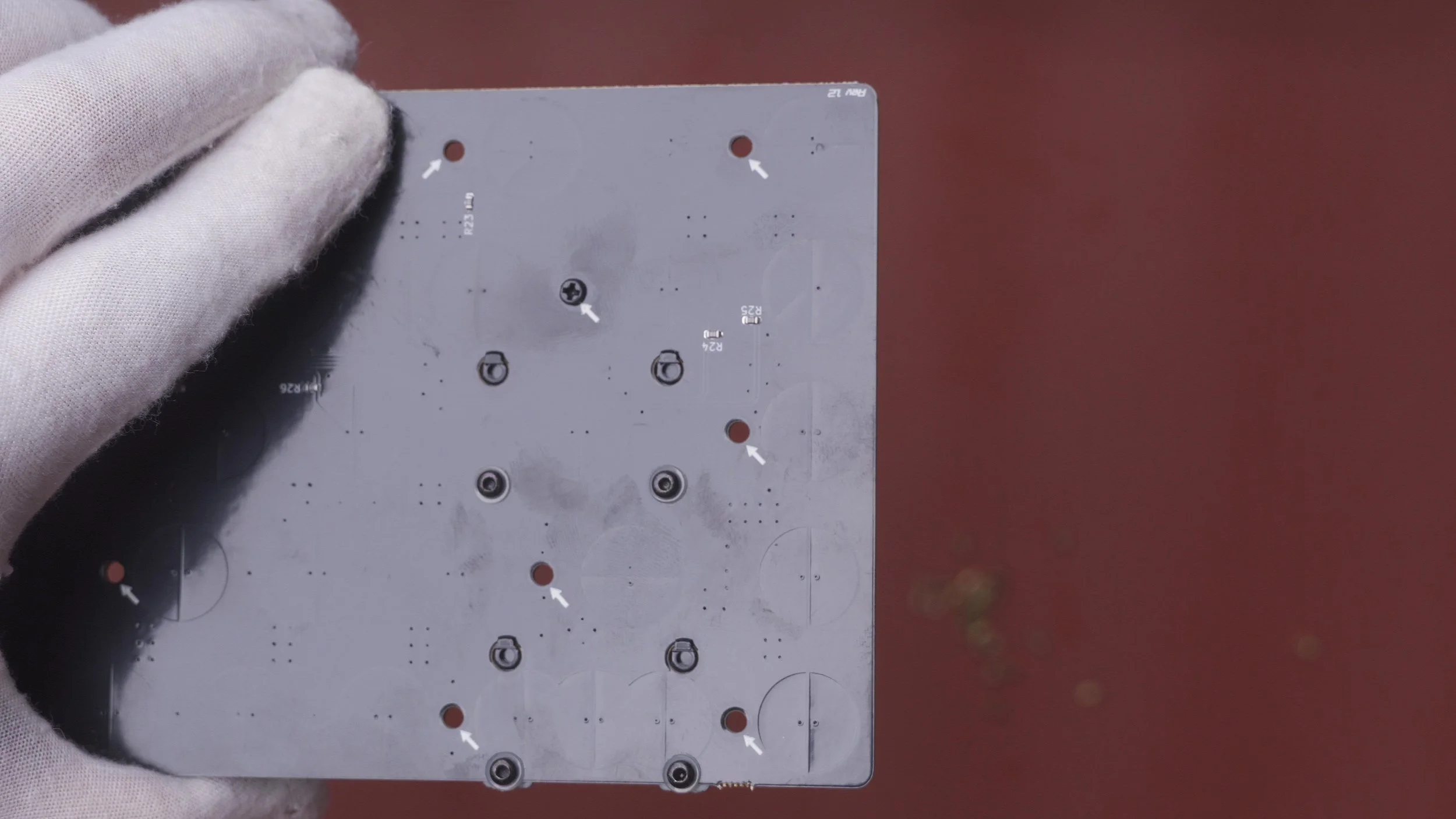
Remove PCB rails
You can use pliers (or your hands) to remove the two PCB technical rails that are at the top and at the bottom of the PCB.
The result of this operation is shown below. You can dispose of the PCB rails. The PCB designer, Cipulot, also provides a friendly reminder on the bottom rail to
“Remember to calibrate the PCB after assembling the board”
We will address this later, on the Calibration section.


Preparing your Stabilizers
Stabilizers are important for rattle-free modifier sound.
One of the merits of these novel EC switches is that it allows the setup to forgo the niche Topre stabilizer standard. It also allows the use of PCB-mount stabilizers that are used for standard MX-compatible builds and maintains standard MX housing cutouts for keyswitches.
Lubrication can be done using greases, such as Krytox 205g0 or dielectric grease, and is applied on moving parts that may cause extraneous noise that is undesirable.
In the case of Staebies, tolerances are on the tighter side, so I only apply lube to the inside of the stem insert (as shown).

Apply lube to the stem inserts
Using a small paintbrush, I gently apply a very light coat of Krytox 205g0 lubricant to the interior part of the stem insert (if you see two holes on the insert, it is the one closer to the “base”). The idea is that lube here will prevent extraneous noise from the contact between the stabilizer wire and the inside of the insert.
As you can see below, I have not applied lubricant to the exterior face of the stem insert. Excess lubricant can cause stickiness and binding of the stabilizer action.


Assemble your stabilizer housing
Once done with the stem insert, insert it into the housing. For proper orientation of the insert, the “notch” on the crucifix (+) should face towards the “back” of the stabilizer; that is, in the same direction as where the end of the wire will be.

Assemble all your stems and housings
Self-explanatory — put together all of your stem inserts into the housings.

Lubing the stabilizer wire
NOTE: This step can vary significantly between stabilizer brands/products. For Staebies v2, relatively minimal lubrication is advised.
First, I apply a light, even coat of Krytox 205g0 on one of the short ends of the wire, down to just around the elbow/bend to the long horizontal section.
Then, I brush a small “bead” or excess of lube towards the end of the wire.
(The photos below depict a bit more lubricant than may be appropriate for use, but you can gauge this from practice and from testing your stabilizers. If your stabilizers feel sticky or heavy after assembly, try using less lube in general, and also do not overtighten screws for screw-in stabilizers.)


Insert the wire into the stabilizer stem
Using one hand, hold the wire. Using the other, orient the stabilizer housing with stem. The wire is to be inserted on the “bottom hole” (in most cases) of the front-facing side of the stabilizer stem inside the housing.
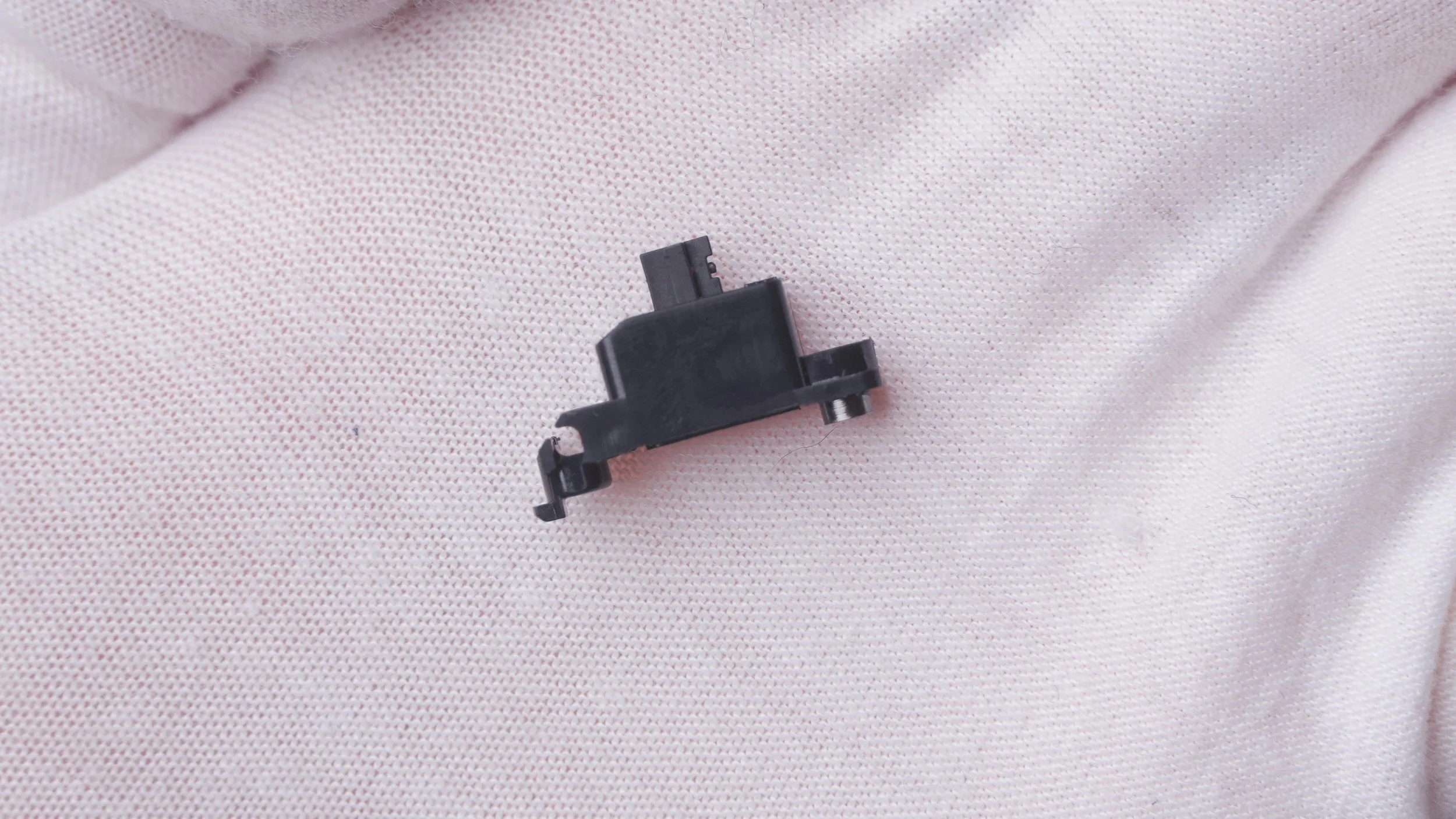
Below you can see an example of an assembled stabilizer part.


Repeat and assemble all stabilizers
Repeat the process of assembling each side of the stabilizer, ensuring that movement of the wire is uninhibited while feeling secure as you move the stem up and down inside the housing.
Below you can see a photo of assembled stabilizers ready to be mounted onto the PCB.


Install stabilizers onto PCB
Once you have completed any preferred tuning of your stabilizers, you can install them onto the PCB.
Stabilizers have an orientation. For example, a “South-facing” stabilizer has the wire with its longer, horizontal segment “pointed South” towards on the bottom side of the assembled piece. Likewise, a “North-facing” stabilizer has the wire on the opposite side. In the photo, you can see an example of a South-facing stabilizer.
To install the stabilizer, the side where the wire elbows are located fits into the larger hole of PCB mounting holes. Hook the stabilizer starting from this end and then fit the other end (threaded insert for screw-ins) into the smaller PCB mounting hole.

Secure stabilizer onto PCB
Using an M2 screw with a washer, secure each side of the slotted-in stabilizer from the bottom side of the PCB.
Do NOT overtighten your screws. You can stop upon facing the slightest resistance, just finger-tight, and ensure they are evenly screwed in.
A well-mounted stabilizer will look as shown below once mounted to the PCB.
Secure all of your stabilizers (4x on the Satellite).


Stabilizers installed!
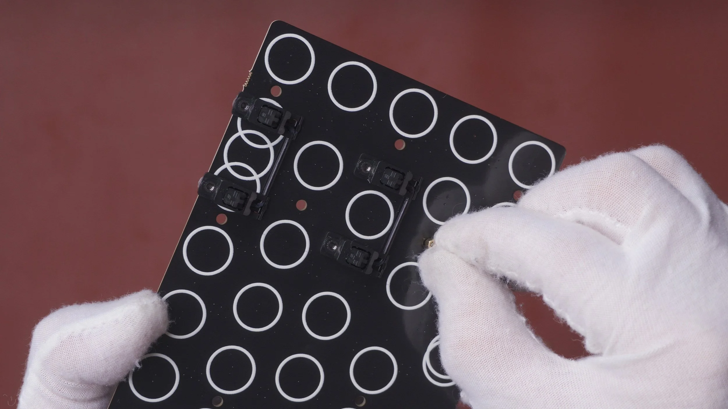
Depicted here are all four stabilizers (3x 2u + 6.25u spacebar) installed onto the Satellite EC PCB. You can double-check placement of your stabilizers by placing the plate on top of the stabilizers. The crucifix portions should come through, and the inserts should come up all the way when you pull onto each side of every stabilizer.
You may choose to test your stabilizer by inserting switches to the plate (read below) on the stabilizer positions. Use a keyswitch puller to remove the keyswitches before standoff installation.

Standoff Installation
Next, we will install standoffs onto the PCB. These will ensure that the PCB and plate are evenly spaced apart at all times for easier slotting of the EC-compatible switches later on.
Grab your PCB with stabilizers, and the two bags labeled
M2 x 3 screw for PCB boards (26 pcs)
M2 x 3.5 screw bolt (spacers or standoffs, 26 pcs)
Installing a Standoff
You can install standoffs in two ways —
You can place a screw from the bottom side of the PCB and hold it as you flip it to right-side up, and then screw on a standoff using your other hand, or
You can hold a standoff from the top-side of the PCB and attach a screw using your other hand from the bottom side of the PCB.
Your choice! I find it easier to follow Method 1, but for those with larger hands/fingers or those standoffs near stabilizers, I opted for Method 2.
Photos here show how I follow Method 1 to attach a standoff.

Standoff Installed
Follow the process described above and attach all of your standoffs. There are a whopping 26 (!) of them, each paired with 26 screws that tighten from the bottom-side of the PCB.
A properly installed stand-off will sit upright and flush to the PCB on the top-side.


All Standoffs Done!
Once you have installed all 26 standoffs. You can double-check that they are secured using a Phillips + screwdriver. Hold each standoff from the top-side using one hand, and tighten the screw to finger-tight using the other.


Plate screw installation
Once standoffs are installed, you can place the EC-compatible plate with standoff-aligned holes on top of the PCB with stabilizers.
The standoffs should line up perfectly with the holes drilled onto the plate. Grab your M2 x 3 screws for plates (26 pcs.), and use a Phillips (+) screwdriver to attach all 26 screws to each standoffs, this time from the top-side of the PCB.


Note regarding the standoff parts
On the left, you can see that the parts for the standoff installation are distinct.
Left: Screw for standoff - goes from bottom-side of PCB, Thicker head.
Middle: Threaded standoff - goes between PCB and plate. Secured using screws
Right: Screw for plate top-side, attaches from above; thinner screw head.
At the end of installation of standoffs, you may be left with 1-2 extras of each part. Don’t worry if you aren’t left with extras, so long as you have attached all 26.

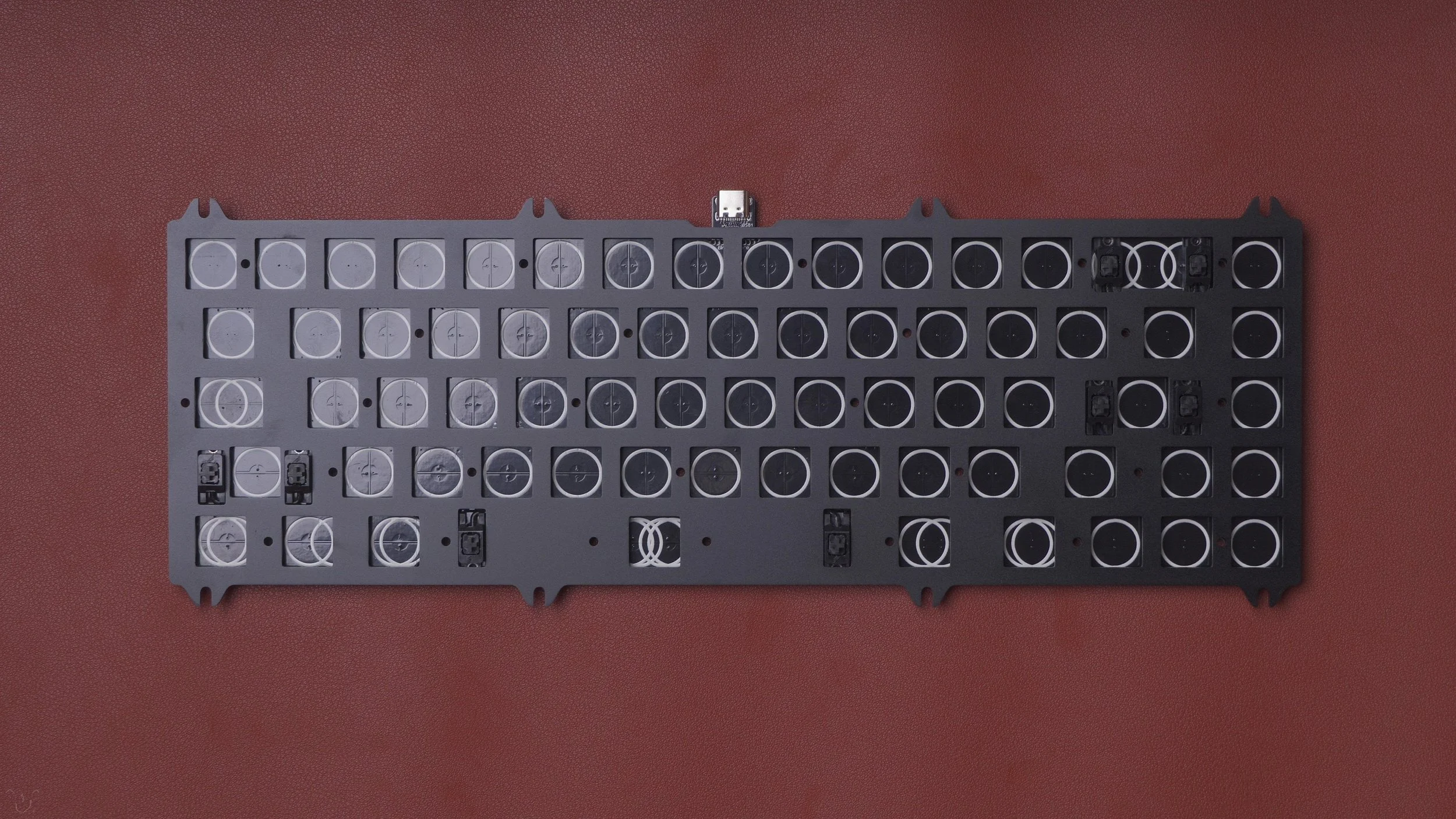
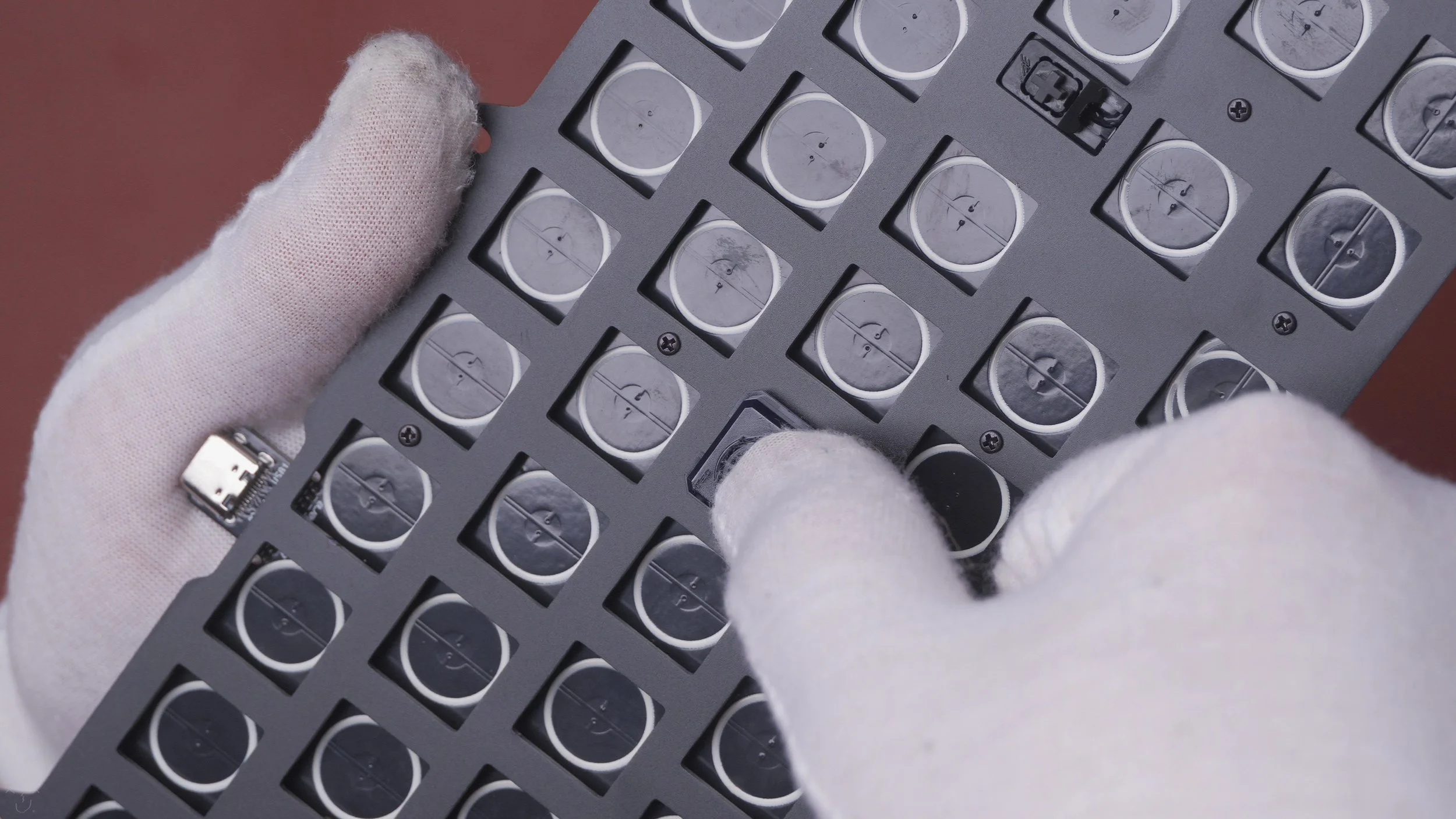
Plate assembly complete
Depicted is a completed PCB-plate assembly with no switches. Your assembly should have:
Secured (4) PCB-mount stabilizers with appropriate stabilizer stem range of motion
Secured (26) standoffs between PCB and plate
Plate secured equidistant from PCB, with matching plate cutouts for keyswitches.

Naevies EC switches
Shown are 70x EC-compatible Naevies switches. These switches are designed to match Topre weighting, which typically is measured by force of actuation (unlike Cherry MX, where spring weightings are often measured to bottom-out). For this build, about 67 switches suffice for the layout.
To ensure proper orientation of the switch clipped to the plate and PCB, you can consider inserting them same-side up, with the readable TEC (Tecsee) logo on the top left, and the AE (AEBoards) logo on the bottom right.

Insert Keyswitches into Plate
To insert each pre-assembled EC keyswitch into the PCB-plate assembly, carefully place the keyswitch into one of the square keyswitch cutouts on the plate. Personally, I like to begin in the middle and near standoffs, to ensure that the plate and PCB remain equally separated throughout the keyswitch attachment process.
No soldering is required at this step on EC builds, as EC switches work by compression of the dome-and-conical-spring onto the PCB.

Insert keyswitches
You may insert keyswitches at random positions of the plate, ensuring that an even distribution maintains a clear, and equidistant separation between PCB and plate. Though the standoffs make this job a lot easier, I enjoy using both of my hands for this process.
Place every EC switch into all single, empty spots including those between stabilizer inserts.

Regular or Stepped - Layout Choices
In some cases, such as for the Caps Lock position, enthusiasts may choose to opt between the vintage-standard Stepped Caps Lock position, or the modern Regular / Full-Touch Caps Lock position. Choose wisely before attaching your switches to these multi-layout support portions.
At this point, you may also (re-)test your stabilizers. A word of advice is to not overtighten screws on screw-in stabilizers.


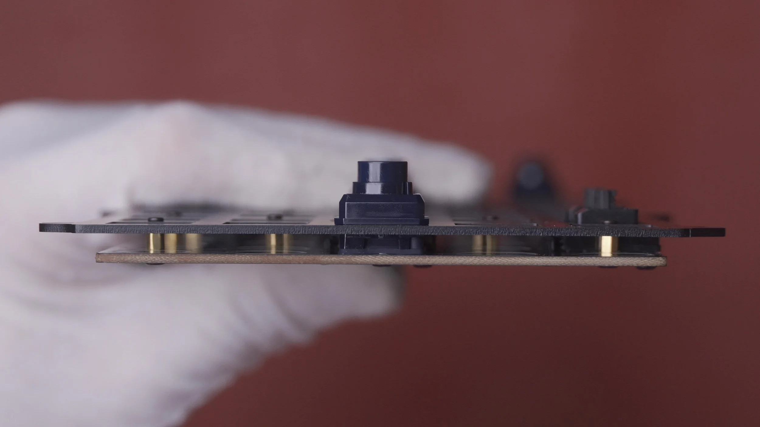
PCB/Plate Assembly Complete!
At this point, you have completed the assembly of the PCB and plate with switches and stabilizers.
Next is the calibration of the EC-compatible PCB. Without it, your PCB will not function properly.
Calibration must be performed each and every time you open up the PCB/plate assembly completely, whether for changing switches / domes or for other reasons.
An excellent EC PCB Calibration Guide video is on YouTube, created by the same designer as many EC-compatible PCBs, Cipulot. Basic calibration steps (identical to those shown in the video) will be described below. You may choose to watch the video and skip this portion.

Calibration (1)
Plug in your PCB using an appropriate USB-C cable connected to your computer.
Using a web browser, open up VIA, an application that we will use to calibrate and/or program your keymap layout.
Navigate to https://caniusevia.com/ and “Try Now! at the top navigation bar.
Once your device is plugged in, you will see “Authorize device” on the screen. Click it and a pop-up will ask you to connect an HID device — select Constellation EC and click Connect.
Note: VIA can only be used on Chromium-based browsers.


Calibration (2)
Once the screen loads up, you will see the currently-mapped keymap of the Constellation EC PCB. Navigate to the leftmost vertical bar and select EC TOOLS at the bottom.
Calibration (3)
Select CALIBRATION and toggle on the Bottoming Calibration.
Next, press firmly, one-by-one, on every keyswitch on the assembly, ensuring that keyswitches fully bottom-out upon each press. Move through the entire assembly’s keys, pressing one key at a time, until you have bottomed out on all keys.
Once you have done so, use your mouse to toggle off the Bottoming Calibration toggle on the VIA screen.

Testing PCB
You can test that calibration has been performed successfully by navigating to the Key Tester tab (stethoscope icon at the center-top of the VIA screen).
Toggle on Key Matrix to see the layout of the Constellation EC PCB and test each key by pressing on each one by one until all testing is completed. All keys will light up if successful.


Mounting the Plate
Once PCB testing is complete, unplug your cable from the PCB.
Prepare your Satellite keyboard case, plate screws (8 units M3 x 5mm), and case screws (8 units M3 x 10mm), along with a matching metric hex screwdriver.
TIP: At this position, you may also test your stabilized modifier keys again to ensure none stick or feel odd prior to assembling the case together.

Top Mount
Open the Satellite case, and flip the top case piece upside down.
Align the plate/PCB assembly, such that the top-mount tabs align with the threaded holes.
Secure the plate using the M3 x 5mm bolts.
Note: The provided EC-compatible plate I had is only compatible with top-mount. The Satellite is also capable of using gasket mount, which require long plate tabs along the edges of the plate.
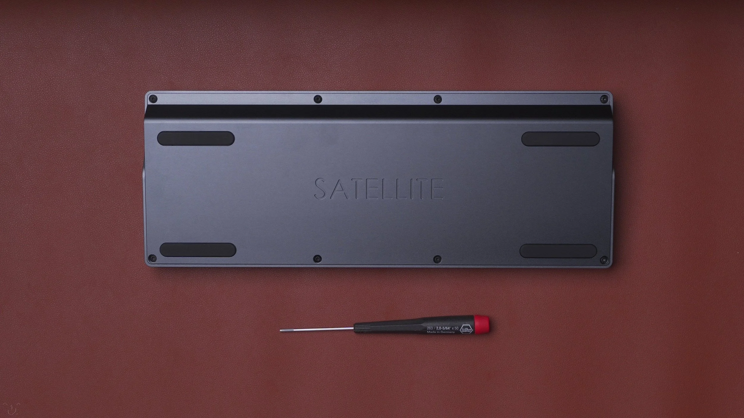
Case Assembly
Once the plate mounting is completed, ensure that the USB-C connector is properly aligned with the USB port hole in the back of the case.
Place the bottom keyboard case piece into the top piece and secure the case pieces together using the available M3 x 10mm bolts.

Assembly Complete
Now assembly is complete and you are ready to mount keycaps.
For this particular build, I require a set with compatible:
Stepped Caps Lock
ANSI layout + 2u Backspace
6.25u spacebar
1.25u (3) and 1.5u (2) modifiers for the bottom row.

Mount Keycaps
Once you have selected your keycaps, mount them onto each keyswitch (and stabilizer, if appropriate).
For modifier keys with stabilizers, you need not use excessive force to mount the keycaps as it may cause the keycap to see-saw and/or stick in the “down” position.
For my build, I chose GMK Oblivion and artisan keycaps by Omniclectic and Nightcaps.
Enjoy your Satellite EC! Happy keyboard-ing.
—
If you have read down to here, thank you for reading, and I hope you found this guide helpful. I don’t create these too frequently as I often teach by livestreaming keyboard builds on Twitch and answering community questions on Discord and other platforms.
Pics of this build can be found here
Satellite
Design by AEBoards.
Grey-anodized aluminum case.
Lubed (205g0) Staebies screw-in stabilizers.
Stock Naevies EC switches with integrated sliders, silencing rings, conical springs, and 45g actuation domes, mounted on an aluminum full plate.
Constellation EC PCB by Cipulot.
GMK Oblivion keycaps